VPLS Settings EcoRouter Documentation / VPLS Settings
- General requirements for VPLS (Martini)
- The circuit with one PE terminating the L2-circuit
- The scheme with three PE, L2-circuit and Service-instance
- VPLS View Commands
- Advanced VPLS settings
The VPLS L2VPN functionality allows the creation of distributed LAN networks over an IP/MPLS network. Unlike VPWS (Virtual Private Wire Service), the VPLS service allows you to create not only point-to-point networks, but also fully-connected L2-networks. EcoRouter also supports the H-VPLS type of service, which allows to terminate not only a physical channel on the VPLS network device, but also pseudowire, representing the combination of VPWS (L2-curciut) and VPLS services.
There are several types of devices, channels and interfaces in the VPLS terminology:
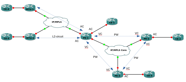
• PW (Pseudowire) - a virtual channel between two PE devices or an MTU and PE device;
• PE (Provider Edge) - the boundary router of the provider network, on which the VPLS service terminates;
• MTU (Multi-Tenant Unit) - a router that terminates VPWS-channels in the direction of the provider's network and physical channels (or VLANs) towards the clients;
• CE (Customer Edge) - client equipment that connects to the provider's equipment - PE or MTU;
• AC (Access circuit) - PE interface towards the client. Can terminate a physical channel or L2-curciut. In EcoRouterOS, a physical channel should be understood as a port, with service-instance and encapsulation untagged or dot1q;
• VC (Virtual circuit) - PE interface towards another PE network. It is a unidirectional virtual channel;
• VSI (Virtual Switch Instance) - virtual Ethernet bridge, terminating AC from clients and VC from the provider's network. VPLS-instance is a synonym for VSI.
The diagram below shows the main devices and channels of the VPLS network.

The VPLS service in EcoRouterOS uses LDP (Martini) signaling. BGP (Kompella) signaling is not supported.
General requirements for VPLS (Martini)
The VPLS service works on top of the IP/MPLS network, accordingly, to organize its operation, it is necessary for IP devices to be connected between PE devices, and MPLS transport based on LDP. There must be a tLDP session between PE devices used to exchange the service MPLS tags.
Similar requirements exist for the connectivity of PE and MTU-r devices. MTU-r devices themselves can be on different networks and do not have IP connectivity with each other.
The circuit with one PE terminating the L2-circuit
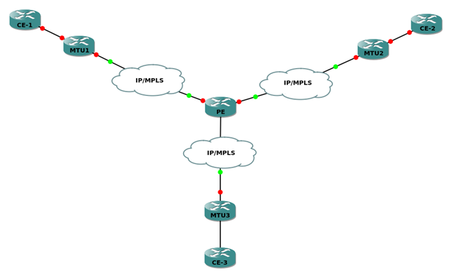
The simplest scheme for using the VPLS service is as follows (see the figure below).

The PE device terminates several L2-circuit channels in one VPLS-domain, as a result of which CE devices are located in the same LAN-network.
MTU-r Settings
On MTU-r devices, the L2-circuit service is configured. These devices do not know anything about VPLS and in principle do not have to support it. An example of setting the L2-circuit can be found in the corresponding section.
PE Settings
PE must be preconfigured with:
- IP-interfaces (see Types of interfaces),
- loopback.0 (see Types of interfaces),
- IGP,
- LDP (see MPLS settings),
- tLDP to MTU-rs.
The configuration mode commands are used to create the L2-circuit:
ecorouter(config)#mpls l2-circuit vc10 10 11.11.11.11
ecorouter(config)#mpls l2-circuit vc20 20 22.22.22.22
ecorouter(config)#mpls l2-circuit vc30 30 33.33.33.33
Where 11.11.11.11, 22.22.22.22 and 33.33.33.33 are the loopback.0 addresses of the MTU-r devices.
VSI is created by the configuration mode command:
ecorouter(config)#vpls-instance test100 100
Where 100 is the VSI ID. After entering the command, the VPLS-instance ecorouter(config-vpls)# context is transitioned to VPLS-instance settings..
To add an L2-circuit to VSI, you use commands in the VPLS-instance context:
ecorouter(config-vpls)#member vpls-vc vc10 ethernet
ecorouter(config-vpls)#member vpls-vc vc20 ethernet
ecorouter(config-vpls)#member vpls-vc vc30 ethernet
The scheme with three PE, L2-circuit and Service-instance
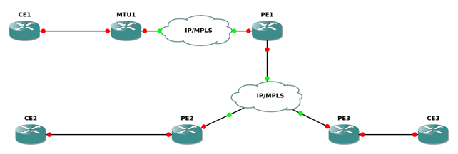
This scheme assumes complete connectivity between PE-devices that connect clients to one LAN-network. Clients are connected to the network by a physical channel (CE2, CE3) and by L2-circuit (CE1).

MTU-r Settings
On MTU-r devices, the L2-circuit service is configured. These devices do not require VPLS support. An example of configuring the L2-circuit can be found in the section MPLS settings.
PE1 Settings
PE1 must be preconfigured with:
- IP-interfaces (see Types of interfaces),
- loopback.0 (see Types of interfaces),
- IGP,
- LDP (see MPLS settings),
- tLDP to MTU-r, PE2 and PE3.
VSI is created by the configuration mode command vpls-instance test100 100, where 100 is the VSI ID (must match all PEs).
After entering the command, the VPLS-instance ecorouter (config-vpls) # context is transitioned to VPLS-instance settings.
To add the L2-circuit to VSI, use the command in the context of VPLS-instance member vpls-vc vc10 ethernet.
To add VPLS neighbors PE2 and PE3, use the following VPLS-instance context commands.
PE1(config-vpls)# signaling ldp
PE1(config-vpls-sig)#vpls-peer 2.2.2.2
PE1(config-vpls-sig)#vpls-peer 3.3.3.3
Where 2.2.2.2, 3.3.3.3 is the loopback.0 of the device addresses PE2 and PE3 respectively.
PE2 Settings
На PE2 must be preconfigured with:
- IP-interfaces (see Types of interfaces),
- loopback.0 (see Types of interfaces),
- IGP,
- LDP (see MPLS settings),
- tLDP to PE1 and PE3.
After entering the command, the VPLS-instance ecorouter (config-vpls) # context is passed to where the vpls-instance settings are executed.
To add a service instance to VSI, use commands in the context of VPLS-instance member port te2 service-instance vpls, where te2 is the port number, and vpls is the service-instance name that must be created on the corresponding port.
To add VPLS neighbors PE2 and PE3, use the following VPLS-instance context commands.
PE1(config-vpls)# signaling ldp
PE1(config-vpls-sig)#vpls-peer 1.1.1.1
PE1(config-vpls-sig)#vpls-peer 3.3.3.3
Where 2.2.2.2, 3.3.3.3 is the loopback.0 of the device addresses PE2 and PE3 respectively.
VPLS View Commands
To view the VPLS-instance status, use the administrative mode commands listed below.The show vpls-instance command shows the basic VSI parameters.
ecorouter#show vpls-instance
Name VPLS-ID Type MPeers SPeers SIG-Protocol
test100 100 Ethernet 0 3 N/A
The show vpls-instance detail command shows more detailed information about the VPLS-instance.
ecorouter#show vpls-instance detail
Virtual Private LAN Service Instance: test100, ID: 100
SIG-Protocol: LDP
Learning: Enabled
Group ID: 0, VPLS Type: Ethernet, Configured MTU: 9714
Description: none
Operating mode: Raw
Configured interfaces:
Interface: vi-100
Mesh Peers: 2.2.2.2 (Up)
3.3.3.3 (Up)
Spoke Peers: vc10 (Up)
To view the MAC address table in VSI, use the show vpls mac-table <NAME> command, where NAME is the VPLS-instance name.
ecorouter#show vpls mac-table test100
VPLS Aging time is 60 sec
L2
Address Port Type Age
-------------- ------- ---------- -----
0050.7966.6801 te2 Dynamic 11
0050.7966.6800 te0 Dynamic 11
Advanced VPLS settings
Aging time
By default, the entry in the switching table is stored for 60 seconds. You can configure the retention time for each VPLS-instance. To do this, use the aging-time <NUM> VPLS-instance context command, where NUM is the storage time in seconds.
ecorouter(config)#vpls-instance test200 200
ecorouter(config-vpls)#aging-time 300
<60-86400> Time in seconds
MTU
By default, MTU (maximum transmission unit) on VPLS-instance is 9710 bytes. MTU is configured for each VPLS-instance. To do this, use the vpls-mtu <NUM> VPLS-instance context command, where NUM is the maximum size of the data unit in bytes.
ecorouter(config)#vpls-instance test200 200
ecorouter(config-vpls)#vpls-mtu 9000
<576-65535> Allowed MTU range
For agreement the peer-neighborhood between the two routers, the MTU of each of them on the VPLS-instance must match. For the correct operation of l2circuit (in case of binding to VPLS-instance), MTU on PE devices and MTU-r must match.


